Description
What is depth from focus?
Depth from focus, also known as focus variation or shape from focus, is a method for obtaining three-dimensional informations from two-dimensional images. Optics with a very small depth of field are used here. A series of images is taken with different positions of the focal plane by changing the distance between the inspected samle and the optics. Due to the camera’s short depth of field, only the parts of the sample within the focal plane are in focus and the area of sharpness “moves” from picture to picture. With the help of algorithms and software, a depth image is generated.
Where is depth from focus used?
A common use case is the inspection of pins. Depth from focus can be used to check if a pin is in the correct position. Furthermore, this method can be used for soldering joint control. The camera is perpendicular to the object which should be checked. This also allows objects (e.g. pins) to be examined which are located in a recess or at the edge of a socket, where other test methods are not possible due to shadowing.
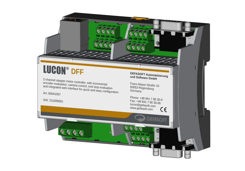
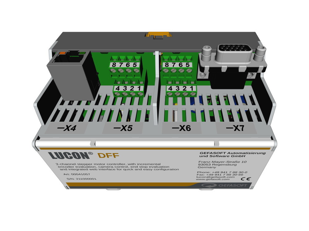
What is LUCON® DFF?
LUCON® DFF offers a cost-effective, flexible and very fast way to use depth from focus. In the LUCON® DFF the control of the focus variation (stepper motor on axis), camera and lighting (an external LUCON® 2 light controller is required for precise illumination control) are combined in one device. Therefore, there is no need for constant communication via slow buses between motor controller, lighting controller and camera. There is also no need to implement a time-consuming and complex synchronisation of these devices via software. LUCON® DFF does this work for you.
The captured image stack then only needs to be evaluated on a computer with the help of algortihms and software (e.g. with Viper.NET from GEFASOFT Automatisierung und Software GmbH).
How does the LUCON® DFF work?
To achieve the highest positioning accuracy, an incremental encoder can be used. The current position is permanently monitored and readjusted if necessary (closed-loop control). In the first step, the desired position is approached. When the position is reached, a trigger signal to one (or more) outputs is activated. These signals are used for the camera and the control of a lighting system. One of the inputs on the LUCON® DFF is now used to detect when the camera is finished with the current acquisition. While the camera transmits the captured image to a computer, the next position is already being approached.

Functional principle of LUCON® DFF
Why use LUCON® DFF?
LUCON® DFF is configured intuitively and conveniently via the integrated, modern web interface. The most important parameters for configuration are:
- Starting position (at which position the first image for the stack is taken)
- Position delta (distance between two images in the stack, typically the step width corresponds to the depth of field of the selected optics)
- Number of images (How many positions are to be approached = number of images in the stack)
There are several ways to configure your depth from focus application. The easiest way is to enter the start position, the distance between the positions and the number of positions. However, it is also possible to set up each position separately. This also makes it possible to vary the distance between the positions.
Flexibly by design
Whether for linear motion or for rotational motion, LUCON® DFF is suitable for both applications. Due to the two completely independent motor channels, a combination of both is also possible. Three switches for position determination are supported per channel: Two end positions and one for the original position. To be compatible with any two phase stepper motor, the supply voltage between controller and motor is completely independent.
Quick and easy configuration
Do you prefer a graphical user interface or command-based communication for configuration? With LUCON® DFF you get both! For command-based communication an ethernet interface with UDP protocol are available. The graphical user interface only requires an ethernet connection and an internet browser - the built-in webserver eliminates the need for further software.
Benefits of the LUCON® DFF
- two independent stepper motor controls
- stepper motor control, incremental encoder evaluation and camera and lighting triggering in one unit
- autonomous operation for very short cycle times
- evaluation of the camera signals for even faster recording
LUCON® DFF was developed by us mainly for use as a depth from focus controller. However, it can be used wherever high positioning accuracy with stepper motors is required. Contact us and tell us about your task.
Do you need a complete image processing system? Our experts from image processing will be happy to help you.
Specification
| Article Number | 00041057 |
| Supply voltage Logic (VIN) | 12 to 24 VDC |
| Supply voltage Motor (VDRIVE) | 5 to 24 VDC |
| Motor Current (IDRIVE) | up to 2.8 A peak |
| Supported microstep resolution | 1, 1/2, 1/4, 1/8, 1/16, 1/32, 1/64, 1/128 and 1/256 |
| Step Frequency | 100 Hz to 1 MHz |
| Supported signal levels for incremental encoder |
TTL (low: -15,0V to +0,8V; high: +2,0V to +15,0V) SE-HTL (low: -15,0V to +6,0V; high: +8,0V to +40,0V) D-HTL (low: differential voltage < -2V; high: differential voltage > +2V) RS-422 (low: differential voltage < -0,45V; high: differential voltage > +0,45V) |
| Supply voltage for incremental encoder | 0V, 5V or VIN (Adjustable via software) |
| Interface | RJ45 @ UDP (with configuration website) |
| Installation | 35 mm DIN top-hat rail, EN50022 |
| Dimensions (w x d x h) | 107,6 mm x 98,4 mm x 60,6 mm |
| Operation temperature | 0 °C - 50 °C |